

What Goes Into a Crane Lift Plan
A crane lift plan is a controlled engineering and operational document that demonstrates a lift can be performed safely before the hook ever leaves the ground. It brings together crane capacity, rigging geometry, ground support, clearances, site hazards, and named responsibilities into one verified package. Whether created on paper, in spreadsheets, or using dedicated lifting plan software, every lift plan must answer the same fundamental questions.
Updated 28 October 2026
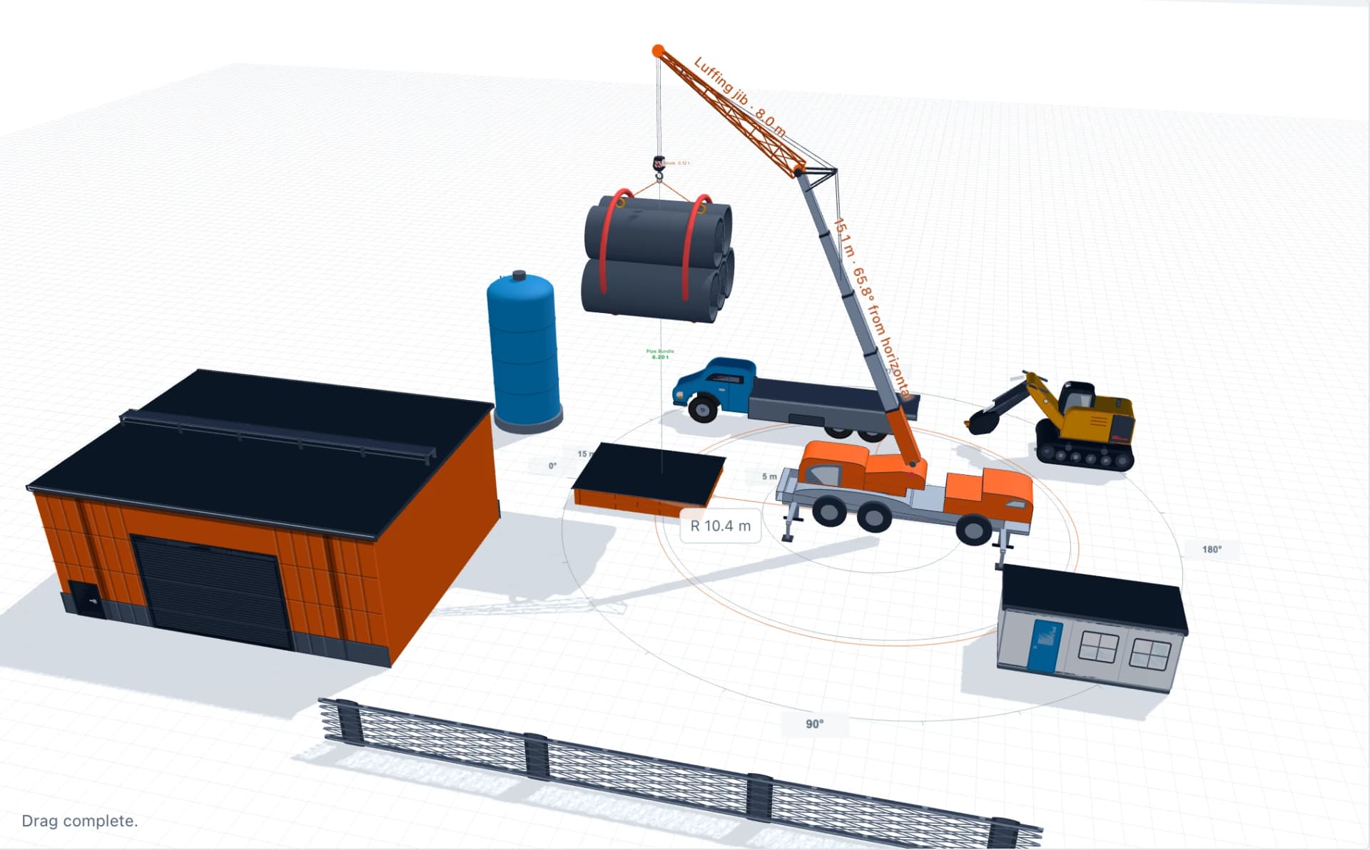
See the whole lift in 3D Top View.
Check the crane, load and site obstacles together before the crane arrives, alongside the range chart and lift plan.
See 3D Top ViewWhy a lift plan is more than a capacity check
A common misconception is that lift planning simply means checking whether a crane’s rated capacity exceeds the weight of the load. Capacity at the working radius is only one link in the chain. Ground that gives way under an outrigger, rigging at a shallow angle, a boom that meets an obstruction, or a misunderstood signal can each cause an incident on a lift that was well within chart capacity.
A complete lift plan documents how the entire system behaves: the crane configuration, the load and its rigging, the ground beneath the pads, the surrounding site geometry, and the people responsible for executing each stage.
Core components every crane lift plan must include
Codes and regulations such as BS 7121 in the UK, and ASME B30.5 and OSHA 29 CFR 1926 Subpart CC in the US, set expectations for how lifting operations are planned and who is responsible. A thorough lift plan typically covers the following:
- 1. Load data and center of gravity — Gross load weight including all components, exact dimensions, center of gravity (especially on asymmetric loads), lift points, and any internal liquid movement or dynamic behaviour.
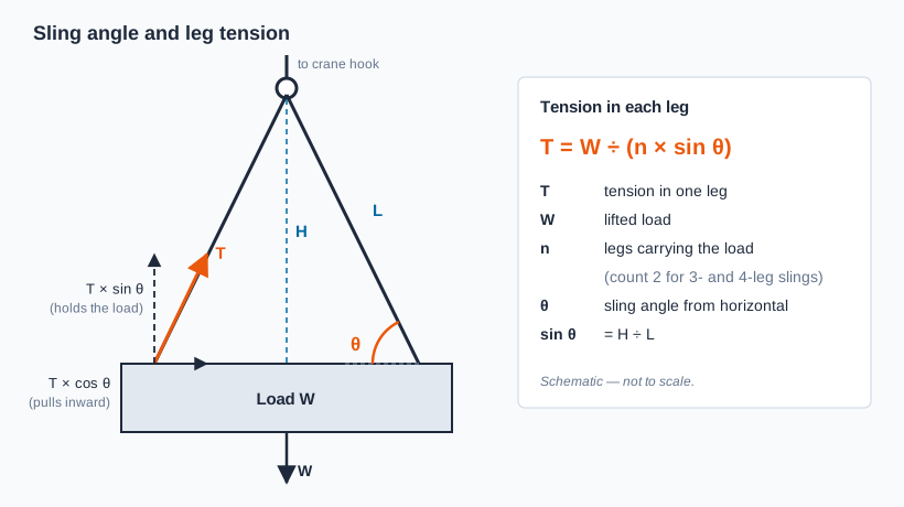
- 2. Rigging tackle and deductions — Weight of the hook block, headache ball, slings, shackles, spreader beams and lifting beams, plus anything else the chart notes require you to deduct. The plan must state sling angles (measured from horizontal), rated sling capacities, and the resulting leg tensions.
- 3. Crane configuration and geometry — Crane make, model, counterweight package, outrigger spread (full, intermediate, or retracted), boom length, boom angle, jib length/offset, operating radius, and maximum tip height required for the pick, swing, and set positions.
- 4. Capacity utilization and safety margins — Rated chart capacity at the maximum pick and place radii, total gross weight (net load + all deductions), and percentage of crane capacity utilized. Many companies and sites set their own utilisation limit, above which a lift is treated as critical and needs extra review.
- 5. Ground conditions and outrigger reactions — Maximum point load on each outrigger pad or track, allowable ground bearing pressure confirmed by geotechnical report or site investigation, and specified crane mat dimensions and material ratings.
- 6. Clearances, obstacles, and exclusion zones — Minimum clearances to buildings, overhead power lines, blind corners, and swing-tail radius. Physical barricading and exclusion zones beneath the load path and counterweight tail-swing area.
- 7. Environmental limits and emergency procedures — Maximum allowable in-service wind speed (for both crane and sail area of load), lightning/gust protocol, ground slope limits, and abort criteria.
- 8. Named personnel and formal sign-offs — Identified Appointed Person / Lift Planner, Crane Operator, Rigging Supervisor / Slinger, and Site Engineer, with dates and sign-off signatures indicating the plan has been reviewed and briefed.
How lifts are categorised
BS 7121-1 expects the level of planning to match the complexity of the lift, and UK practice commonly groups lifts as basic, standard or complex. Organisations word these categories differently — some add an intermediate category — so follow your own procedures. The table shows the typical pattern.
| Category | Typical characteristics | Typical planning |
|---|---|---|
| Basic | Known or easily established weight, no significant hazards from the site or surroundings. | A generic risk assessment and method statement may be enough. |
| Standard | Site-specific hazards, such as lifting over an obstacle or into a restricted area. | Site-specific risk assessment and lift plan prepared by the appointed person. |
| Complex | Multiple cranes, lifting people, or exceptional hazards such as live process plant or public areas. | Detailed, site-specific lift plan with additional engineering review. |
Spreadsheets vs. Dedicated lifting plan software
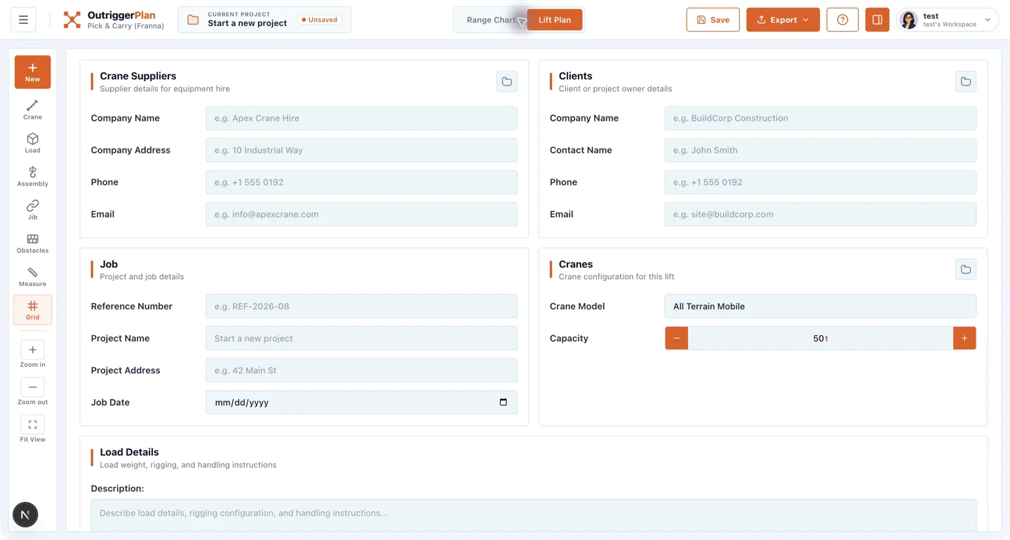
Many planners still work from hand sketches and spreadsheets. A spreadsheet handles arithmetic well, but it has limits on site:
| Factor | Spreadsheet | Dedicated lift planning software (typical) |
|---|---|---|
| Spatial checks | Numbers only — no picture of the boom against buildings or obstacles | Draws the boom, load and site objects so clearances can be checked visually |
| Units | Easy to mix metric and imperial values without noticing | Units shown on inputs and results |
| Use on site | Usually needs a laptop; printed copies go out of date | Runs on phones, tablets and desktops; OutriggerPlan works offline on mobile, macOS and Windows |
| Formula integrity | Cells can be overwritten or broken without anyone noticing | Calculations are built into the app and cannot be edited by accident |
Step-by-step: How to build a professional lift plan
- Step 1: Gather verified load and site data — Confirm the certified weight from a shipping manifest or load cell. Measure the load envelope and locate lift lugs. Inspect the site for underground utilities, excavations, ground bearing capacity, and overhead hazards.
- Step 2: Position the crane and determine radii — Determine the crane setup location that minimizes working radius while maintaining required tail-swing and outrigger clearance. Measure the initial pick radius and the final placement radius.
- Step 3: Select crane configuration and calculate deductions — Choose the appropriate boom length, counterweight, and outrigger spread. Add the hook block weight, headache ball, slings, and rigging hardware to the net load weight to calculate the total gross load.
- Step 4: Check capacity and calculate sling tensions — Confirm that total gross load is within the crane’s rated capacity at the worst-case radius. Calculate sling leg tensions with Tension = Load ÷ (Load-bearing legs × sin θ), counting no more than two legs for three- and four-leg slings.
- Step 5: Verify outrigger pad pressure and mat sizing — Obtain the maximum single-leg outrigger reaction from manufacturer data or verified engineering charts. Divide reaction force by mat area to confirm ground bearing pressure is below the site allowable limit.
- Step 6: Brief the crew and execute sign-off — Review the completed plan during the pre-lift toolbox talk with the operator, riggers, signal person, and lift director. All parties verify that site conditions match the plan before work commences.
What lifting plan software cannot do
- It cannot verify whether the ground has unmapped voids, sinkholes, or soft backfill beneath the surface.
- It cannot replace an on-site physical inspection of slings, shackles, and rigging hardware for wear, cracks, or deformation.
- It cannot approve a lift or replace the authority of a qualified crane operator or appointed person to stop the job if conditions change.
Software is a planning and verification tool designed to eliminate calculation and spatial errors. The final responsibility for safe execution always rests with the competent persons on site.
Common questions
Is there free crane lift planning software available?
Yes. OutriggerPlan’s free calculators (ground bearing pressure, outrigger reaction screening, mat size, sling angle load and lift radius) need no sign-up, and the free plan includes range charts, lift planning and calculations with offline use on mobile, macOS and Windows. PDF lift plan export, website load charts and 3D Top View are included with the Solo and Team plans.
Can I use Excel spreadsheets for crane lift plans?
For simple arithmetic, yes. But a spreadsheet cannot show the boom against site obstacles, and formulas can be overwritten without anyone noticing. Dedicated lift planning software keeps the geometry, the calculations and the record of the plan together.
What is the difference between net capacity and gross capacity?
Gross capacity is the value shown on the manufacturer’s load chart. Net capacity is what is left for the load after subtracting the deductions listed in the chart notes — typically the hook block or overhaul ball, slings, shackles and other rigging, and on some charts items such as an erected or stowed jib.
Who is legally responsible for signing off a crane lift plan?
In the UK, BS 7121 gives the Appointed Person responsibility for planning the lifting operation. In the US, ASME B30.5 sets out duties for roles including the lift director, and OSHA 29 CFR 1926 Subpart CC requires qualified and competent persons for specific tasks. Your company procedures name who signs the plan.
Plan the whole lift in OutriggerPlan
Draw the range chart, check clearances to site objects, run the calculations and record the lift plan. Free on mobile, macOS and Windows, with PDF export and 3D Top View on Solo and Team.